
A reinforced concrete beam is designed as a two-span beam with a cantilever. The cross-section varies along the length of the cantilever (tapered cross-section). The internal forces, the required longitudinal and shear reinforcement for the ultimate limit state are calculated.

The model is based on the example 4 of [1]: Point-supported slab.
The flat slab of an office building with crack-sensitive lightweight walls is to be designed. Inner, border and corner panels are to be investigated. The columns and the flat slab are monolithically joined. The edge and corner columns are placed flush with the edge of the slab. The axes of the columns form a square grid. It is a rigid system (building stiffened with shear walls).
The office building has 5 floors with a floor height of 3.000 m. The environmental conditions to be assumed are defined as "closed interior spaces". There are predominantly static actions.
The focus of this example is to determine the slab moments and the required reinforcement above the columns under full load.
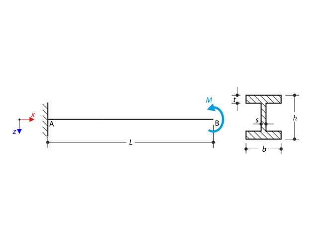
A cantilever of I-profile is supported on the left end and it is loaded by the torque M. The aim of this example is to compare the fixed support with the fork support and to investigate the behaviour of some representative quantities. The comparison with the solution by means of plates is also made. The verification example is based on the example introduced by Gensichen and Lumpe.
A simply supported beam is loaded by pure bending. Determine the critical load and corresponding load factor due to lateral buckling.
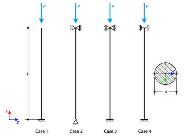
A strut with a circular cross-section is supported according to four basic cases of Euler buckling and subjected to pressure force. Determine the critical load.
A rectangular steel plate of dimensions is simply supported at its edges. Determine the natural frequencies of the rectangular plate.
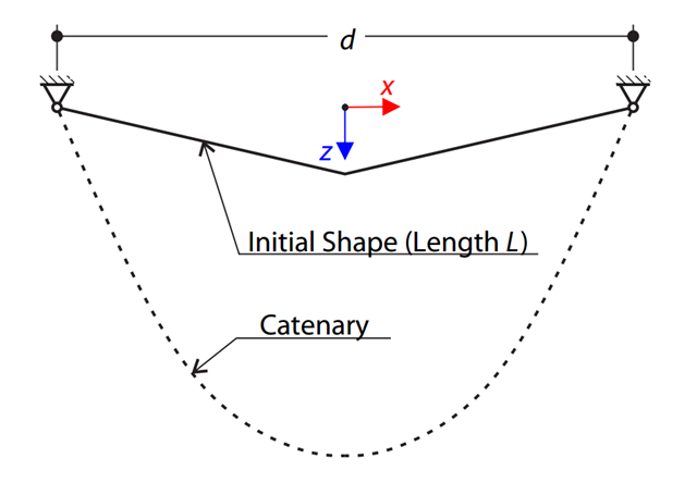
A very stiff cable is suspended between two supports. Determine the equilibrium shape of the cable (the catenary), consider the gravitational acceleration, and neglect the stiffness of the cable. Verify the position of the cable at the given test points.
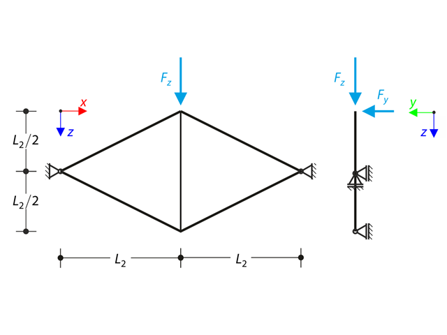
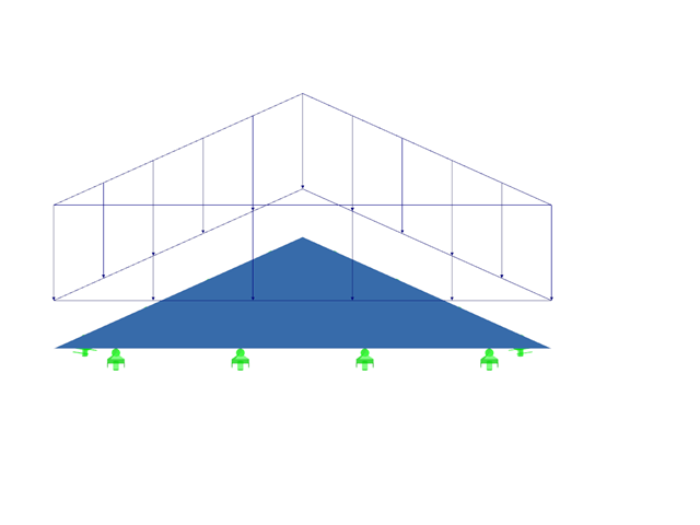
Planar truss consisting of four sloped members and one vertical member is loaded at the upper node by means of the vertical force Fz and out of plane force Fy. Assuming large deformation analysis and neglecting self-weight, determine the normal forces of the members and the out of plane displacement of the upper node uy. The verification example is based on the example introduced by Gensichen and Lumpe.
The model is based on the example 4 of [1]: Point-supported slab. The internal forces and the required longitudinal reinforcement can be found the in verification example 1022. In this example, punching is examined in the axis B/2.

In this verification example, the capacity design values of shear forces on beams are calculated in accordance with EN 1998-1, 5.4.2.2 and 5.5.2.1 as well as the capacity design values of columns in flexure in accordance with 5.2.3.3(2). The system consists of a two span reinforced concrete beam with a span length of 5.50m. The beam is part of a frame system. The results obtained are compared with those in [1].
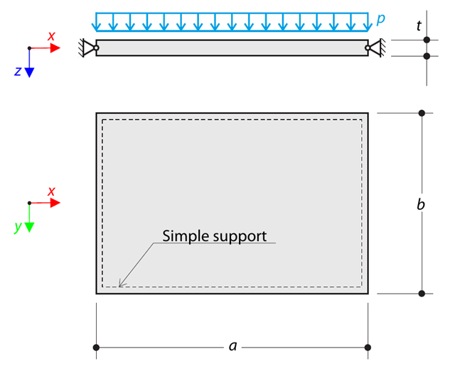
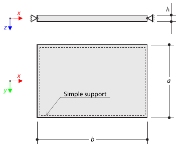
A thin rectangular orthotropic plate is simply supported and loaded by uniformly distributed pressure. The directions of axes x and y coincide with the principal directions. While neglecting self-weight, determine the maximum deflection of the plate.
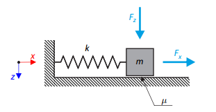
A simple oscillator consists of mass m (considered only in the x-direction) and linear spring of stiffness k. The mass is embedded on a surface with Coulomb friction and is loaded by constant-in-time axial and transverse forces.
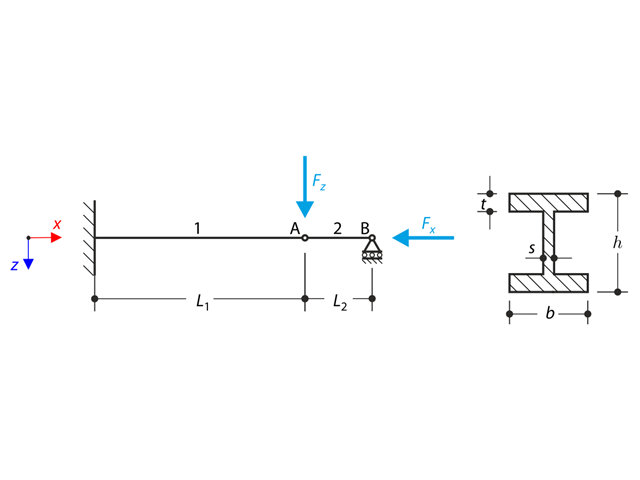
A structure made of I-profile is fully fixed on the left end and embedded into the sliding support on the right end. The structure consists of two segments. The self-weight is neglected in this example. Determine the maximum deflection of the structure uz,max, the bending moment My on the fixed end, the rotation &svarphi;2,y of the segment 2 and the reaction force RBz by means of the geometrically linear analysis and the second-order analysis. The verification example is based on the example introduced by Gensichen and Lumpe.
A simply supported equilateral triangular plate is subjected to a uniformly distributed transverse load. Assuming the small deformation theory and neglecting self‑weight, the maximum out‑of‑plane deflection of the plate is determined.
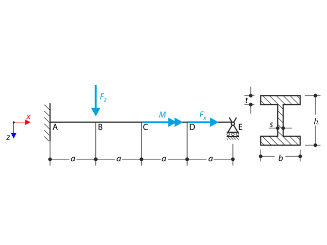
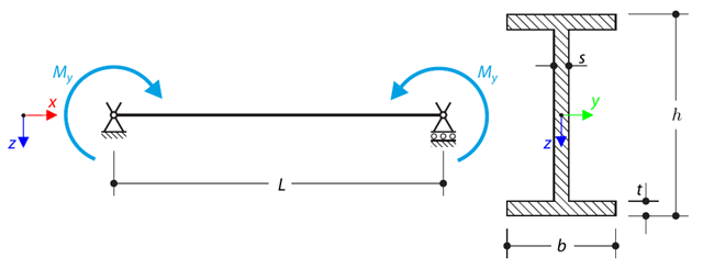
A beam is fully fixed (warping is restricted) on the left end and supported by a fork support (free warping) on the right end. The beam is subjected to a torque, longitudinal force, and transverse force. Determine the behavior of the primary torsional moment, secondary torsional moment and warping moment. The verification example is based on the example introduced by Gensichen and Lumpe (see reference).
A planar truss structure is simply supported. The aim of this verification example is to determine the natural frequencies of the structure.

Using AISC Manual tables, determine the available compressive and flexural strengths and whether the ASTM A992 W14x99 beam has sufficient available strength to support the axial forces and moments shown in Figure 1, obtained from a second-order analysis that includes P-𝛿 effects.
An I-profile cantilever is supported on the left end and loaded by torque. The aim of this example is to compare the fixed support with the fork support and to investigate the behavior of some representative quantities. Comparison is also made to the solution by means of plates. Small deformations are considered, and the self-weight is neglected. Determine the rotation in the midpoint of the cantilever, and in case of the member entity with warping, determine the values of the primary torsional moment, the secondary torsional moment, and the warping moment both on the left end (point A) and the right end (point B).
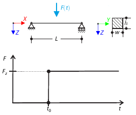
A concentrated force is suddenly applied at the mid‑span of a simply supported beam at a given time. Considering only the small deformation theory, determine the maximum deflection of the beam.
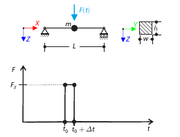
A concentrated force is applied for a short period of time at the mid‑span of a simply supported beam. Considering only the small deformation theory and assuming that the mass of the beam is concentrated at its mid‑span, determine its maximum deflection.